| Services |
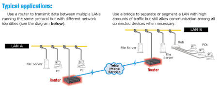
Routers and Bridges Routers and bridges link two or more individual Local Area Networks (LANs) to create an extended-network LAN or Wide Area Network (WAN). Routers A router stores and forwards data packets—each of which contains a destination and source network address—from one LAN or WAN to another. Routers are "smarter" than bridges, because they find the best route for all the data sent to them by the previous router or the end station of the LAN. Routers operate on the third layer of the OSI Model, the Network-Control Layer. Rather than passing packets based on the Media Access Control (MAC) Layer addresses (as bridges do), a router examines the packet's data structure and determines whether or not to forward it. This determination is made based on the network information within the packet. Once the router determines where the packet should be sent, it finds the fastest route to send the data to its destination. The router also has to send this data in the most appropriate format for transferring information. That means it may repackage or break the data into smaller pieces than the receiving destinations can handle. Routers don't have a bridge's ability to learn addresses, so they have to do more data processing than bridges do. Routers also have to be aware of the network protocols they serve and often have more complex installation and configuration requirements. Occasionally a router encounters a protocol it doesn't understand. If this occurs, it typically just drops the packet. Some protocols are considered "nonroutable"—they don't define any network information in the data packet. However, most routers have bridging capabilities. They can bridge nonroutable protocols by checking a packet's destination address and simply sending protocols through, so you don't lose information. The most popular "routable" protocols are IPX™/SPX, TCP/IP, and AppleTalk®. If a router doesn't have bridging capabilities, it automatically discards any packets it encounters with nonroutable protocols, such as NetBIOS, LAT™, or SNA. Bridges A bridge connects two LAN segments into one larger continuous LAN. So how does a bridge operate? Unlike routers, every bridge builds an internal list of addresses of the attached network devices on both sides of it. When a bridge sees a packet, it checks the packet's address against its internal list. If the destination address is on the opposite segment or if the bridge doesn't have the address logged, the bridge forwards the information. Bridges operate at the Data-Link Layer of the OSI Model. They can distinguish between local and remote data, so data traveling from one workstation to another in the same segment doesn't have to cross the bridge. Bridges operate on MAC-Layer addresses. They're protocol independent, so they transfer data between workstations without having to understand the protocol. That means they require little or no configuration. The OSI Model for Open
Systems Interconnection. Manufacturers are developing intelligent computers and equipment, and numerous private and public data networks have been created to connect it. But communication among these distributed systems and networks requires a standard approach to network design, one that defines the relationships and intersections between network services and functions via common interfaces and protocols. The layered approach to network architecture stems from the operating system (OS) design. Because of their complexity, most computer OSs are developed in sections, each of which has a particular function. This makes it simpler to refine each section to meet its functional goal. Ultimately, all sections are integrated to provide complete capabilities and services with a smooth-running OS. The same is true in designing networking systems. A network architecture specifies a hierarchy of independent layers that contain modules for performing defined functions. This translates into a set of rules that defines the way participating network nodes must interact to communicate and exchange information. The OSI Model defines standard relationships between the hardware and software in today's complex computer systems.
Each layer of the OSI Model (shown above) provides specific services that contribute to overall network functioning.
|
||||||||||||||||||||||||||||||||||||||||||||||||||||||||||||||||||||||||||||||||||||||||||||||||||||||||||||||||||||||||
| ► | Software Development | ||||||||||||||||||||||||||||||||||||||||||||||||||||||||||||||||||||||||||||||||||||||||||||||||||||||||||||||||||||||||
| ► | Web Based Notification and Messaging | ||||||||||||||||||||||||||||||||||||||||||||||||||||||||||||||||||||||||||||||||||||||||||||||||||||||||||||||||||||||||
| ► | Network Design, Management, and Security | ||||||||||||||||||||||||||||||||||||||||||||||||||||||||||||||||||||||||||||||||||||||||||||||||||||||||||||||||||||||||
| ► | Network Backup and Continuity Planning | ||||||||||||||||||||||||||||||||||||||||||||||||||||||||||||||||||||||||||||||||||||||||||||||||||||||||||||||||||||||||
| ► | Remote Site and Incident Location Networking | ||||||||||||||||||||||||||||||||||||||||||||||||||||||||||||||||||||||||||||||||||||||||||||||||||||||||||||||||||||||||
| ► | Remote Access Solutions - VPNs | ||||||||||||||||||||||||||||||||||||||||||||||||||||||||||||||||||||||||||||||||||||||||||||||||||||||||||||||||||||||||
| ► | Database Server Management | ||||||||||||||||||||||||||||||||||||||||||||||||||||||||||||||||||||||||||||||||||||||||||||||||||||||||||||||||||||||||
| ► | Wireless Data Solutions | ||||||||||||||||||||||||||||||||||||||||||||||||||||||||||||||||||||||||||||||||||||||||||||||||||||||||||||||||||||||||
| ► | Rogue Wireless Data Detection | ||||||||||||||||||||||||||||||||||||||||||||||||||||||||||||||||||||||||||||||||||||||||||||||||||||||||||||||||||||||||
| ► | Firewall and Intrusion Detection Solutions | ||||||||||||||||||||||||||||||||||||||||||||||||||||||||||||||||||||||||||||||||||||||||||||||||||||||||||||||||||||||||
| ► | Network and Data Security | ||||||||||||||||||||||||||||||||||||||||||||||||||||||||||||||||||||||||||||||||||||||||||||||||||||||||||||||||||||||||
| ► | Automation Project Management | ||||||||||||||||||||||||||||||||||||||||||||||||||||||||||||||||||||||||||||||||||||||||||||||||||||||||||||||||||||||||
| ► | Web & Email Group Survey Systems | ||||||||||||||||||||||||||||||||||||||||||||||||||||||||||||||||||||||||||||||||||||||||||||||||||||||||||||||||||||||||
| ► | Data Mining - Data Analysis - Geocoding | ||||||||||||||||||||||||||||||||||||||||||||||||||||||||||||||||||||||||||||||||||||||||||||||||||||||||||||||||||||||||
| ► | Technology Consulting and Education Services | ||||||||||||||||||||||||||||||||||||||||||||||||||||||||||||||||||||||||||||||||||||||||||||||||||||||||||||||||||||||||
| ► | Seminar and Conference Organization and Management | ||||||||||||||||||||||||||||||||||||||||||||||||||||||||||||||||||||||||||||||||||||||||||||||||||||||||||||||||||||||||
| Products / Downloads | |||||||||||||||||||||||||||||||||||||||||||||||||||||||||||||||||||||||||||||||||||||||||||||||||||||||||||||||||||||||||
|
► |
Software | ||||||||||||||||||||||||||||||||||||||||||||||||||||||||||||||||||||||||||||||||||||||||||||||||||||||||||||||||||||||||
|
► |
Hardware | ||||||||||||||||||||||||||||||||||||||||||||||||||||||||||||||||||||||||||||||||||||||||||||||||||||||||||||||||||||||||
|
► |
Policy Samples | ||||||||||||||||||||||||||||||||||||||||||||||||||||||||||||||||||||||||||||||||||||||||||||||||||||||||||||||||||||||||
|
Articles ► Articles Presentations |
|||||||||||||||||||||||||||||||||||||||||||||||||||||||||||||||||||||||||||||||||||||||||||||||||||||||||||||||||||||||||
| ► | Presentations | ||||||||||||||||||||||||||||||||||||||||||||||||||||||||||||||||||||||||||||||||||||||||||||||||||||||||||||||||||||||||
| Technical Documents | |||||||||||||||||||||||||||||||||||||||||||||||||||||||||||||||||||||||||||||||||||||||||||||||||||||||||||||||||||||||||
| ► | Ethernet Overview | ||||||||||||||||||||||||||||||||||||||||||||||||||||||||||||||||||||||||||||||||||||||||||||||||||||||||||||||||||||||||
| ► | High Speed Networking | ||||||||||||||||||||||||||||||||||||||||||||||||||||||||||||||||||||||||||||||||||||||||||||||||||||||||||||||||||||||||
| ► | Frame Relay Overview | ||||||||||||||||||||||||||||||||||||||||||||||||||||||||||||||||||||||||||||||||||||||||||||||||||||||||||||||||||||||||
| ► | Fiber Optics | ||||||||||||||||||||||||||||||||||||||||||||||||||||||||||||||||||||||||||||||||||||||||||||||||||||||||||||||||||||||||
| ► | Routers and Bridges | ||||||||||||||||||||||||||||||||||||||||||||||||||||||||||||||||||||||||||||||||||||||||||||||||||||||||||||||||||||||||
| ► | Digital Subscriber Lines (xDsL) | ||||||||||||||||||||||||||||||||||||||||||||||||||||||||||||||||||||||||||||||||||||||||||||||||||||||||||||||||||||||||
| ► | Category 5 Cabling and Beyond | ||||||||||||||||||||||||||||||||||||||||||||||||||||||||||||||||||||||||||||||||||||||||||||||||||||||||||||||||||||||||
| ► | Serial Data Transmission | ||||||||||||||||||||||||||||||||||||||||||||||||||||||||||||||||||||||||||||||||||||||||||||||||||||||||||||||||||||||||
| ► | Universal Service Ordering Code (USOC) | ||||||||||||||||||||||||||||||||||||||||||||||||||||||||||||||||||||||||||||||||||||||||||||||||||||||||||||||||||||||||
| ► | Universal Serial Bus (USB) and Firewire | ||||||||||||||||||||||||||||||||||||||||||||||||||||||||||||||||||||||||||||||||||||||||||||||||||||||||||||||||||||||||
| ► | dBm to Watt Conversion | ||||||||||||||||||||||||||||||||||||||||||||||||||||||||||||||||||||||||||||||||||||||||||||||||||||||||||||||||||||||||
| Company Information | |||||||||||||||||||||||||||||||||||||||||||||||||||||||||||||||||||||||||||||||||||||||||||||||||||||||||||||||||||||||||
| ► | About CPCS Technologies | ||||||||||||||||||||||||||||||||||||||||||||||||||||||||||||||||||||||||||||||||||||||||||||||||||||||||||||||||||||||||
| ► | Contact Information | ||||||||||||||||||||||||||||||||||||||||||||||||||||||||||||||||||||||||||||||||||||||||||||||||||||||||||||||||||||||||
| Links / Resources | |||||||||||||||||||||||||||||||||||||||||||||||||||||||||||||||||||||||||||||||||||||||||||||||||||||||||||||||||||||||||
|
► |
Additional Resources | ||||||||||||||||||||||||||||||||||||||||||||||||||||||||||||||||||||||||||||||||||||||||||||||||||||||||||||||||||||||||
|
|
|||||||||||||||||||||||||||||||||||||||||||||||||||||||||||||||||||||||||||||||||||||||||||||||||||||||||||||||||||||||||